Day 1
The Motivation
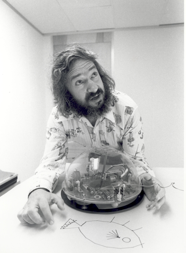 So this started when I saw these videos online. Being the bona fide Ed Tech junky I am, I've always been a huge Seymour Papert fan. His book Mindstorms is still one of my favourite educational reads and the logo programming he did with kids in the late '70's and early '80's has always had a place in my heart as one of the coolest Ed Tech projects of all time.
The role of the teach is to create the conditions for invention rather than provide ready-made knowledge.
So when I found an opportunity to create a "draw-bot" my mind immediately went to his turtle-bots. Here's the two first videos I checked out that inspired me to try this project that was obviously way over my head.
There are literally hundreds of versions of this CNC type project online. Some use DVD drives like this one, some use old printer components, some take this the next step and replace the pen with a laser cutter or 3D extruding pen to make a 3D printer. The cool thing is that you're learning how to control X, Y, and Z axis' and mashing together a number of programs and languages to get it done. To be honest this project is WAY over my skill level, but hey, you'll never know your boundaries if you don't try and push them, right?!
The Plan
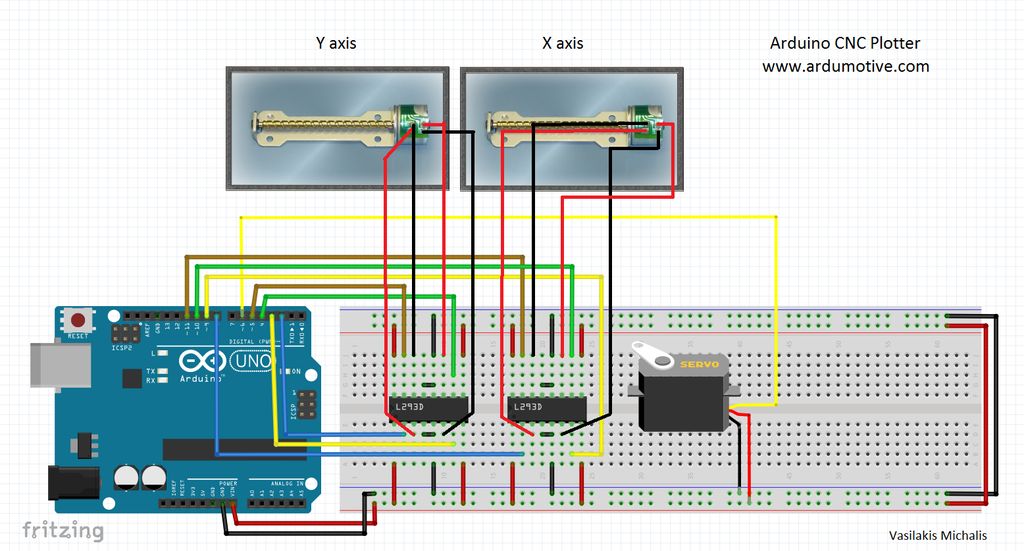
So the project files I decided to follow are from ARDUinoautoMOTIVE. Lots of cool projects there so check them out! They've got a great break down of what you need and the software and code they used here; http://www.ardumotive.com/new-cnc-plotter.html
So what do I need?
 Starting with ARDUinoMOTIVE's list I changed a few things out just to make things a little cleaner.
- Arduino UNO

L293D Motor Driver Shield Breadboard2x L293D ICs Motor driver- L293D Motor Driver Shield ($9 from MakerVault.com)
- Mini Servo Motor (scavenged from a broken remote control car)
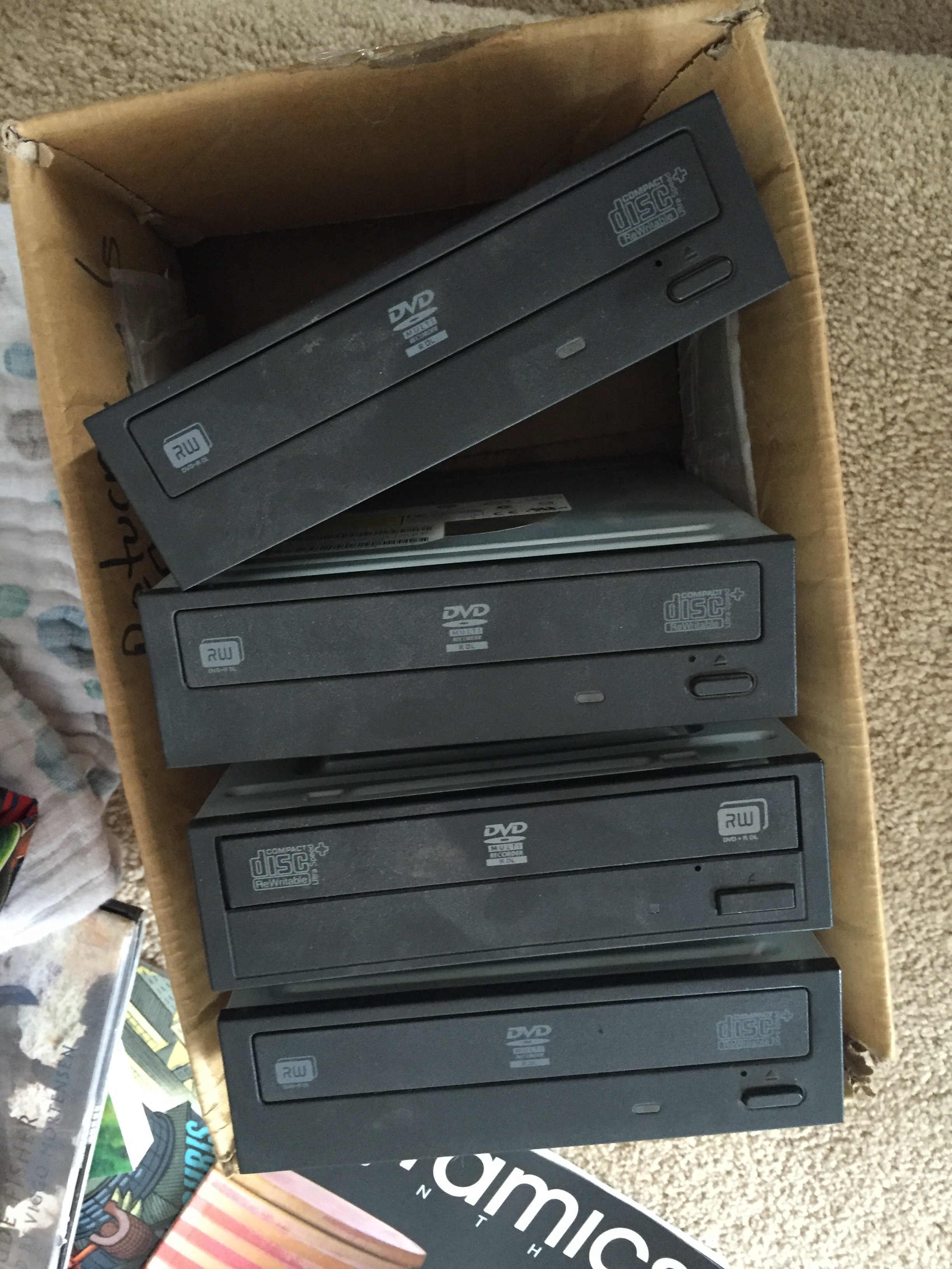
- 3x DVD/CD Drives ($2 each on kijiji)
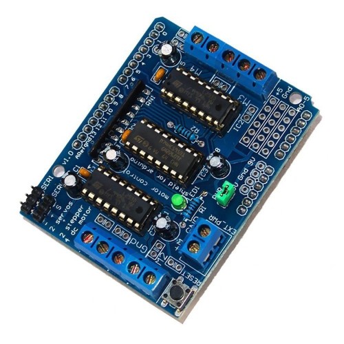
I changed out a few things and will give it a try just to clean up the wiring and such. I didn't want to use a breadboard and wires because I wanted the CNC to be something I could basically plug and play with the Arduino so I bought a motor controller shield from MakerVault.com which combines the breadboard and the 2 L293D Motor Drivers onto a plug and play shield for the Arduino UNO, which I already have. This way, I'll be able to have it all wired up to the cheap $9 motor controller board and when I want to use it I just have to plug it into the Arduino and run the code. The only issue is that I'll have to alter the code a bit because I assume I'll need to include a different library of commands for this board than I would have needed for the hardware included in the ARDUinoMOTIVE list. But we're getting ahead of ourselves. Let's take a look at the hardware construction of this CNC machine first.
The Machine
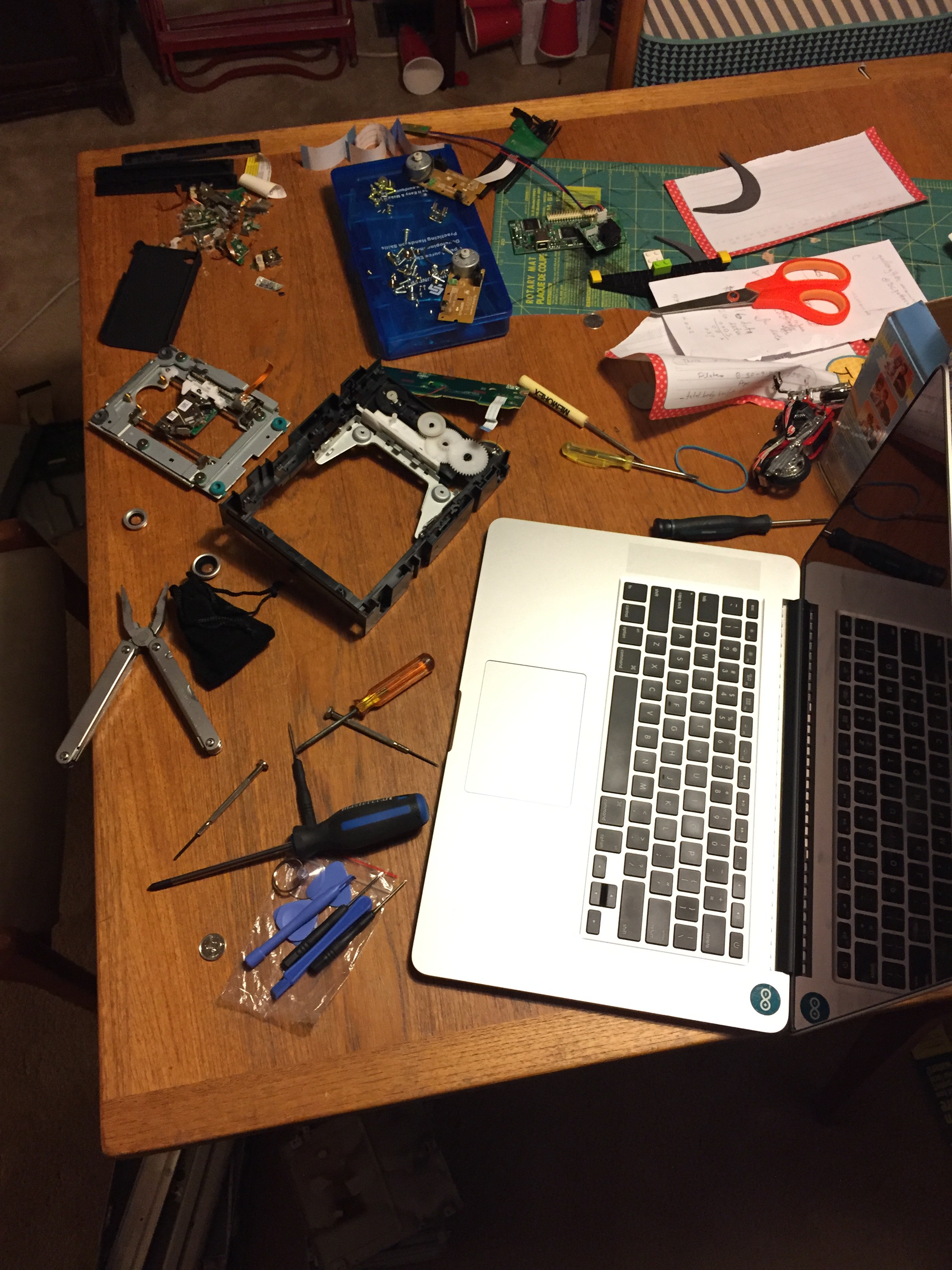
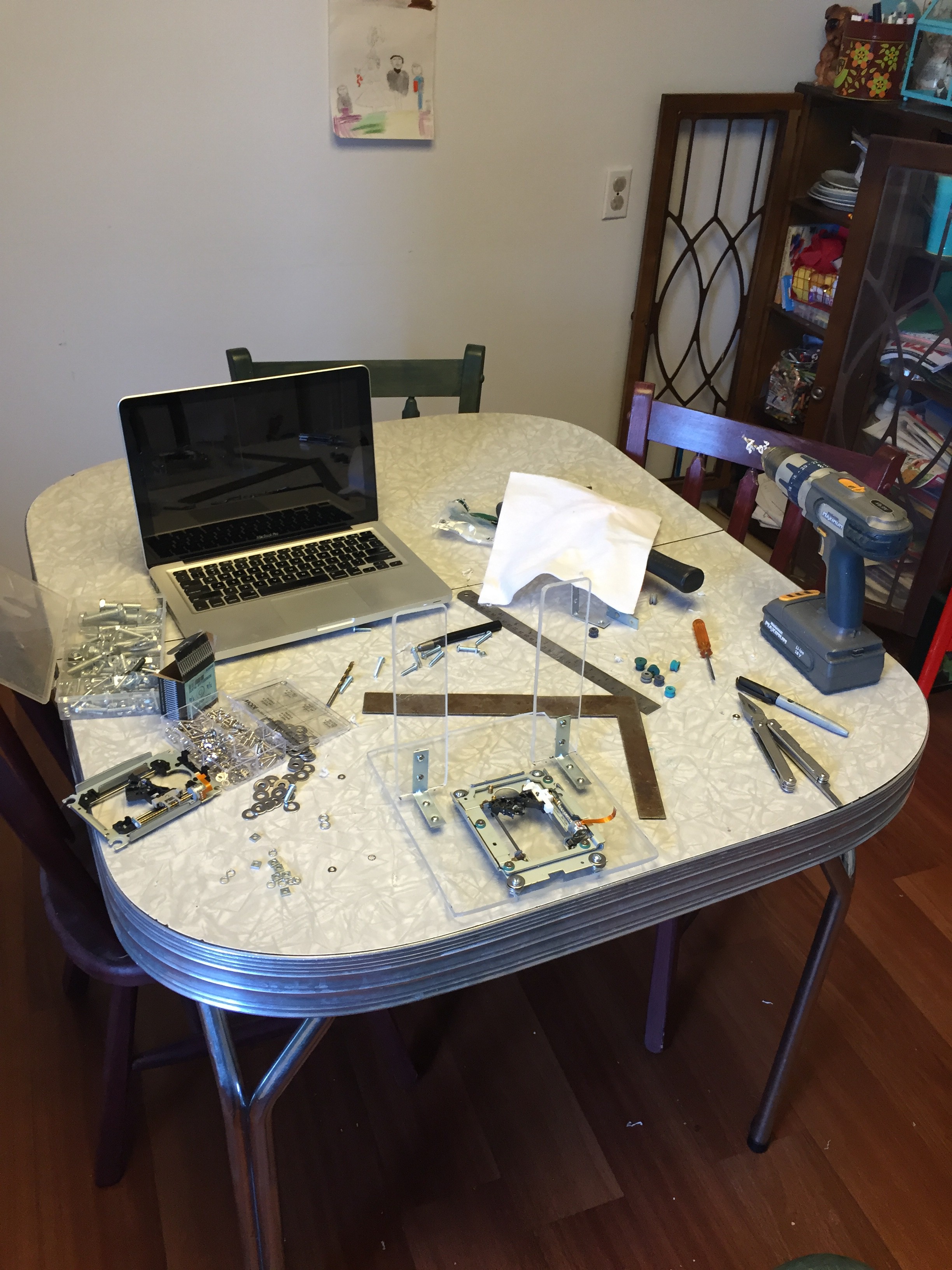
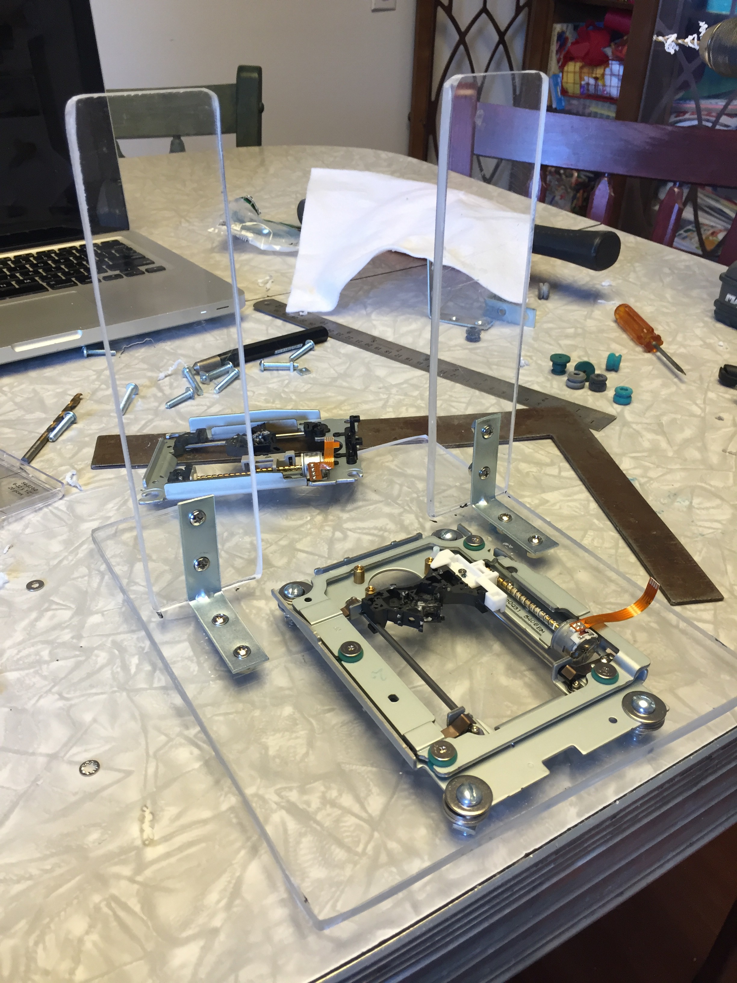
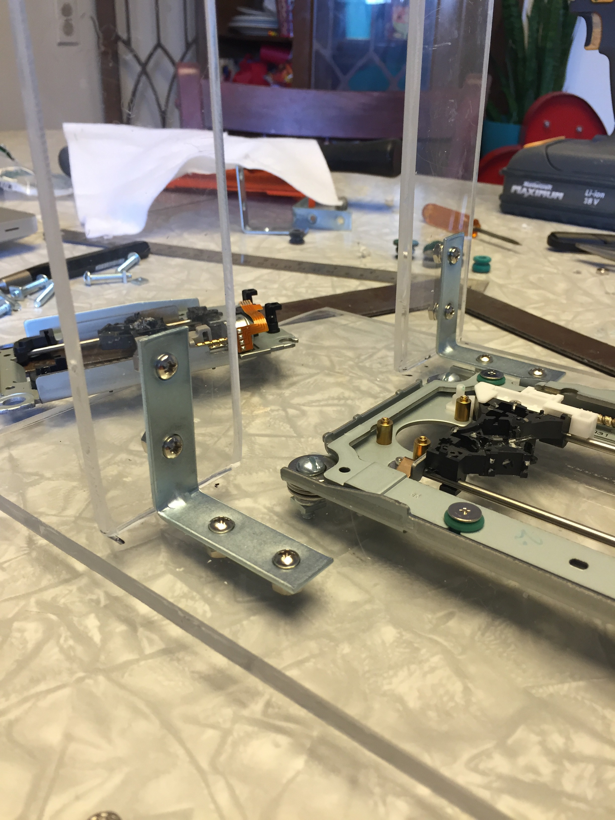
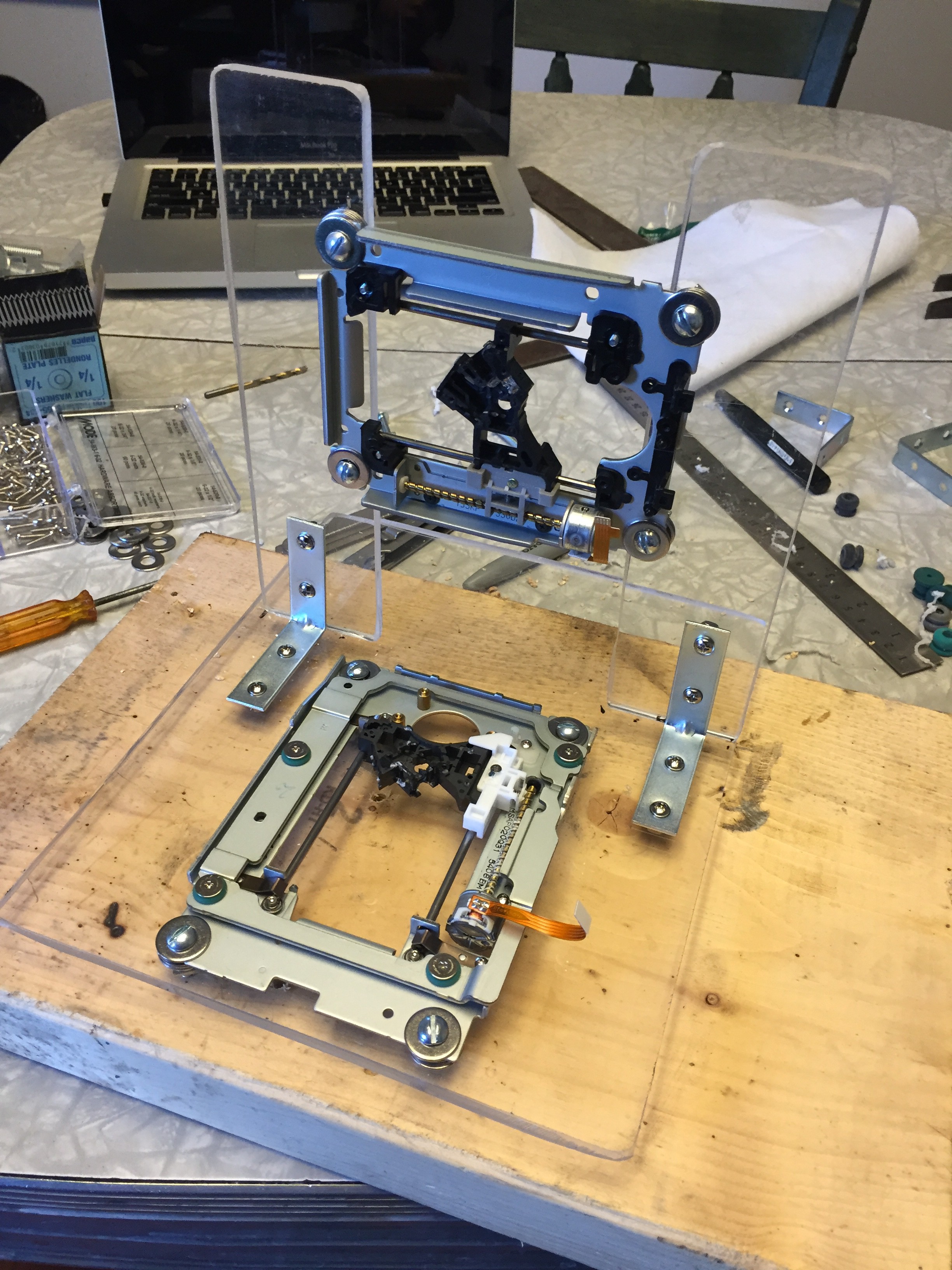
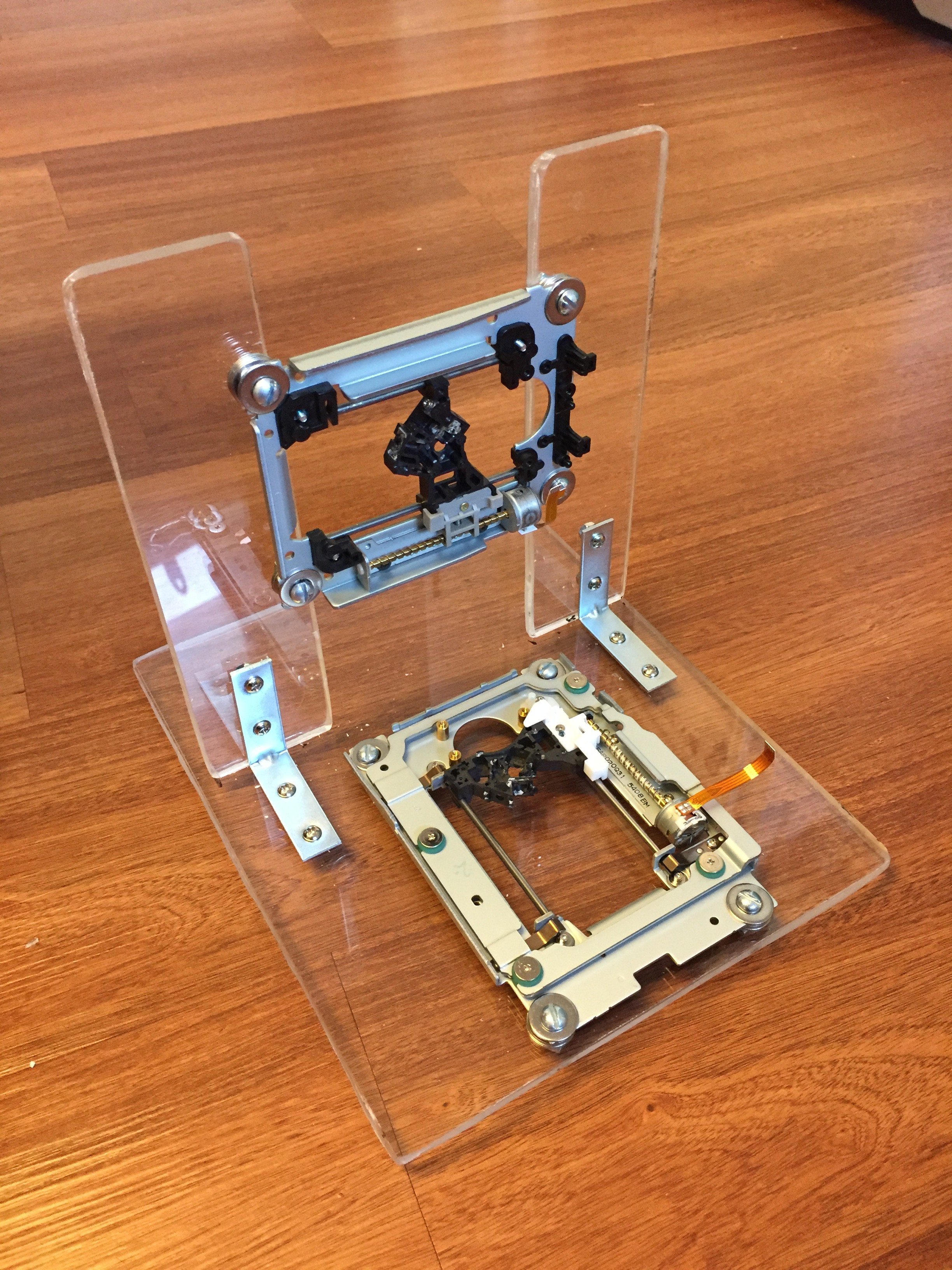
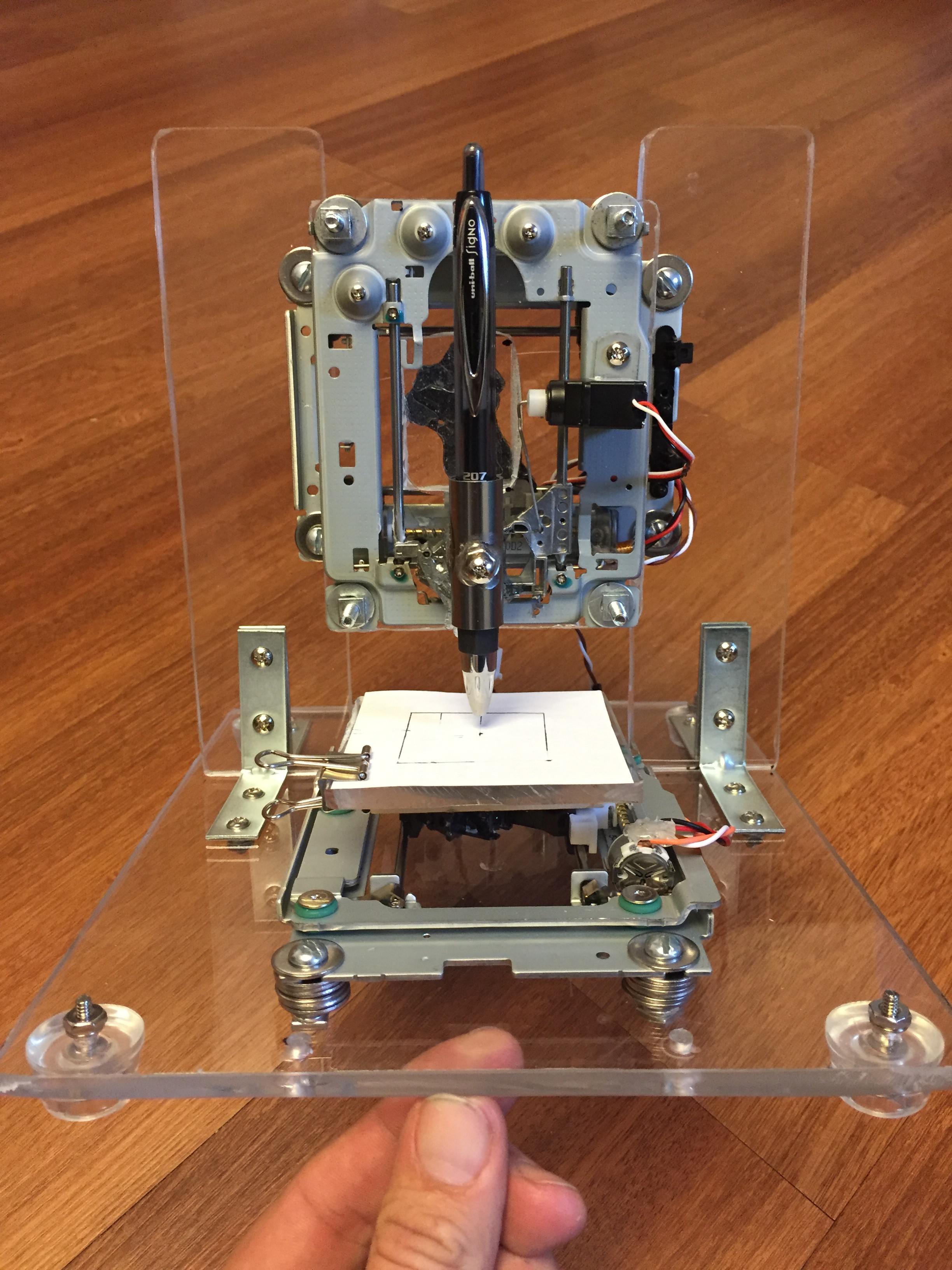
So the first thing I needed was some old DVD-ROM drives from some old desktop computers. These are getting harder and harder to find as you can imagine. But a quick Kijiji search and Voila! I picked these 4 drives up for $2 a piece. Then it's just a matter of getting into the motor and rail system. Once I had two DVD rail and motor chassis removed it was time to start thinking about how the frame for the CNC would be constructed. I found an old piece of plexiglass in the basement that was going to be perfect. So I cut some pieces that I thought looked similar to the ARDUinoMOTIVE folks and started drilling and bolting things together. It's very important that everything is well aligned so measuring with squares and angle finders can really help a lot. I needed to do a little readjusting when I realized that the X axis wasn't going to get under the Y axis far enough to use the whole drawing surface, but it all turned out. Here's some shots of the build on day 1.
Day 2
Z axis
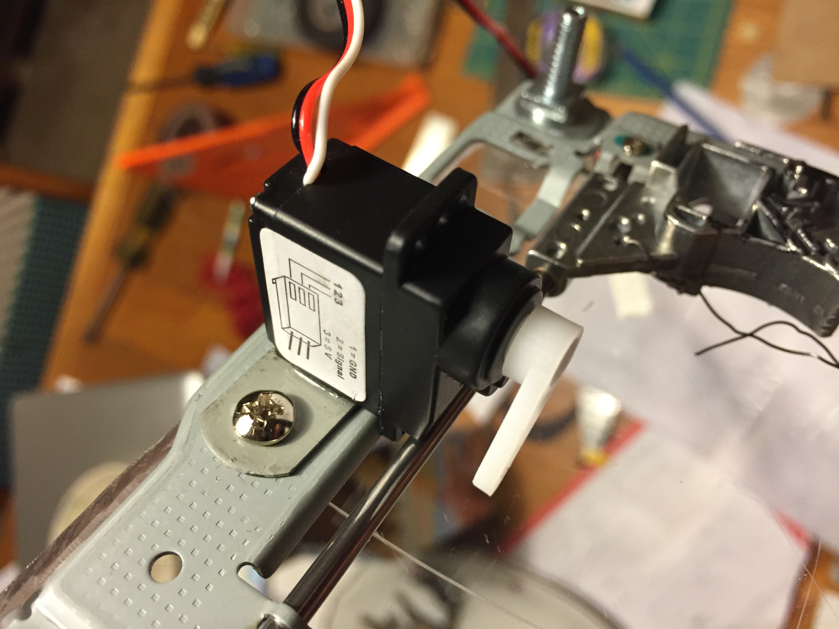
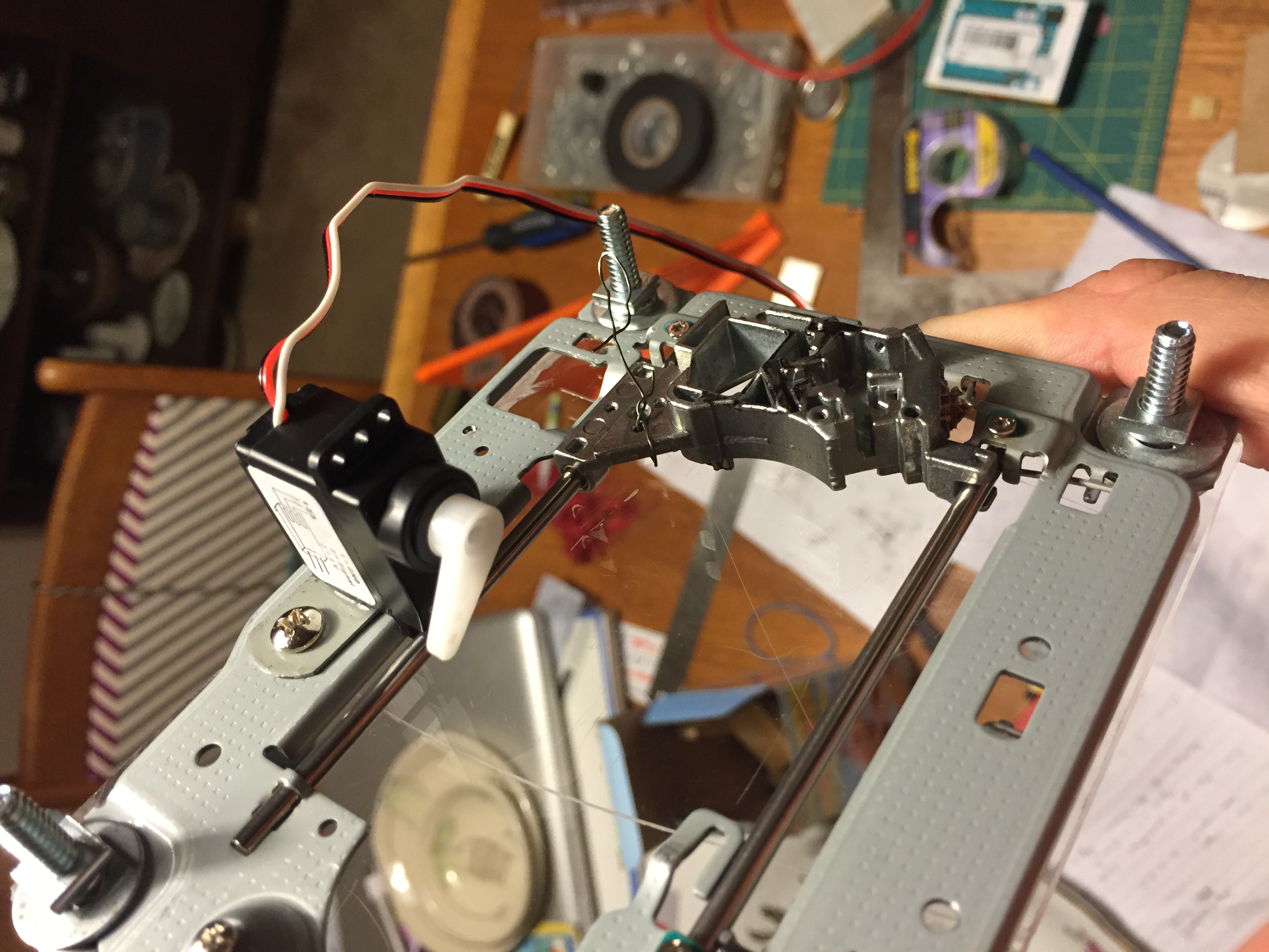
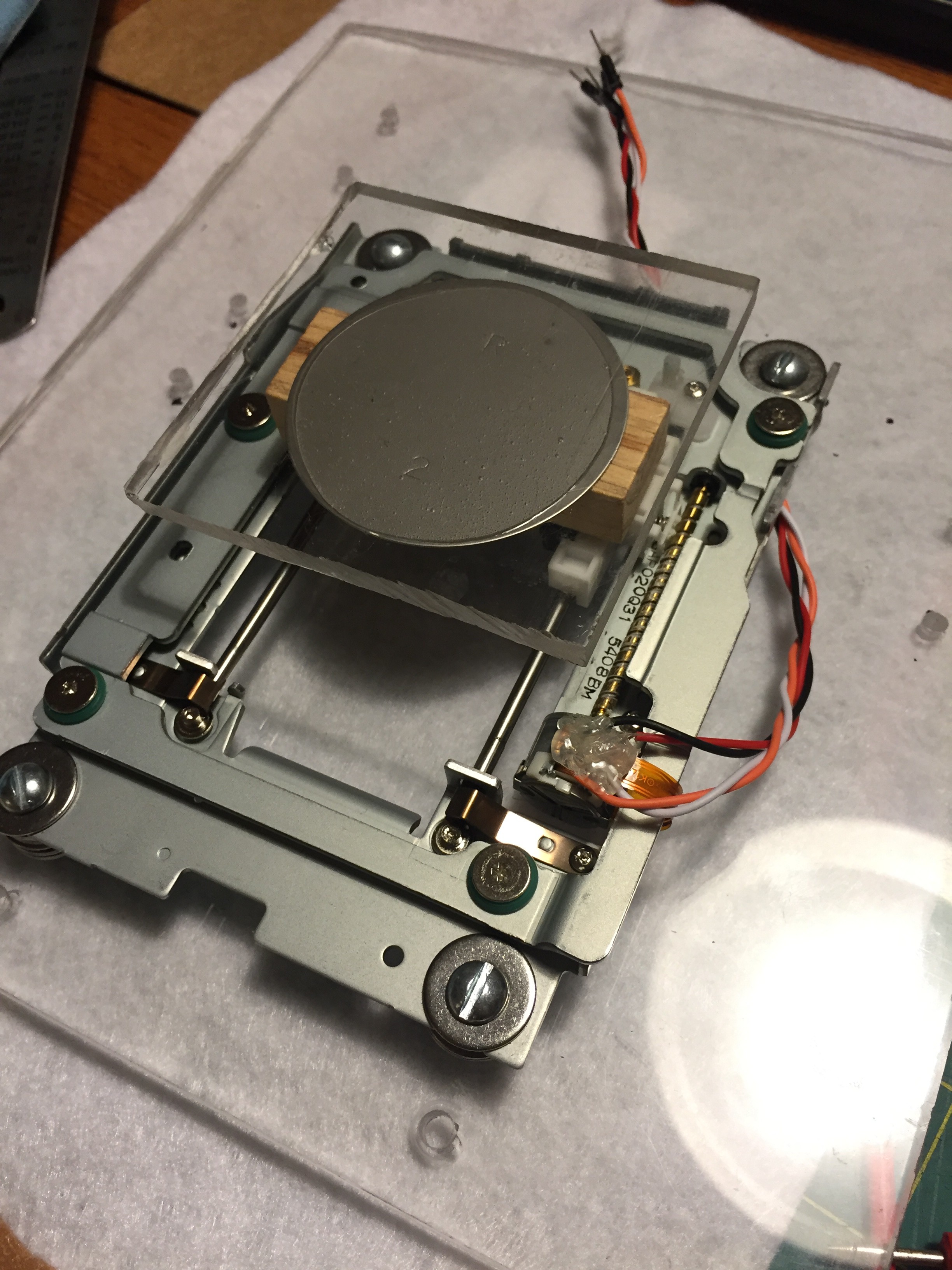
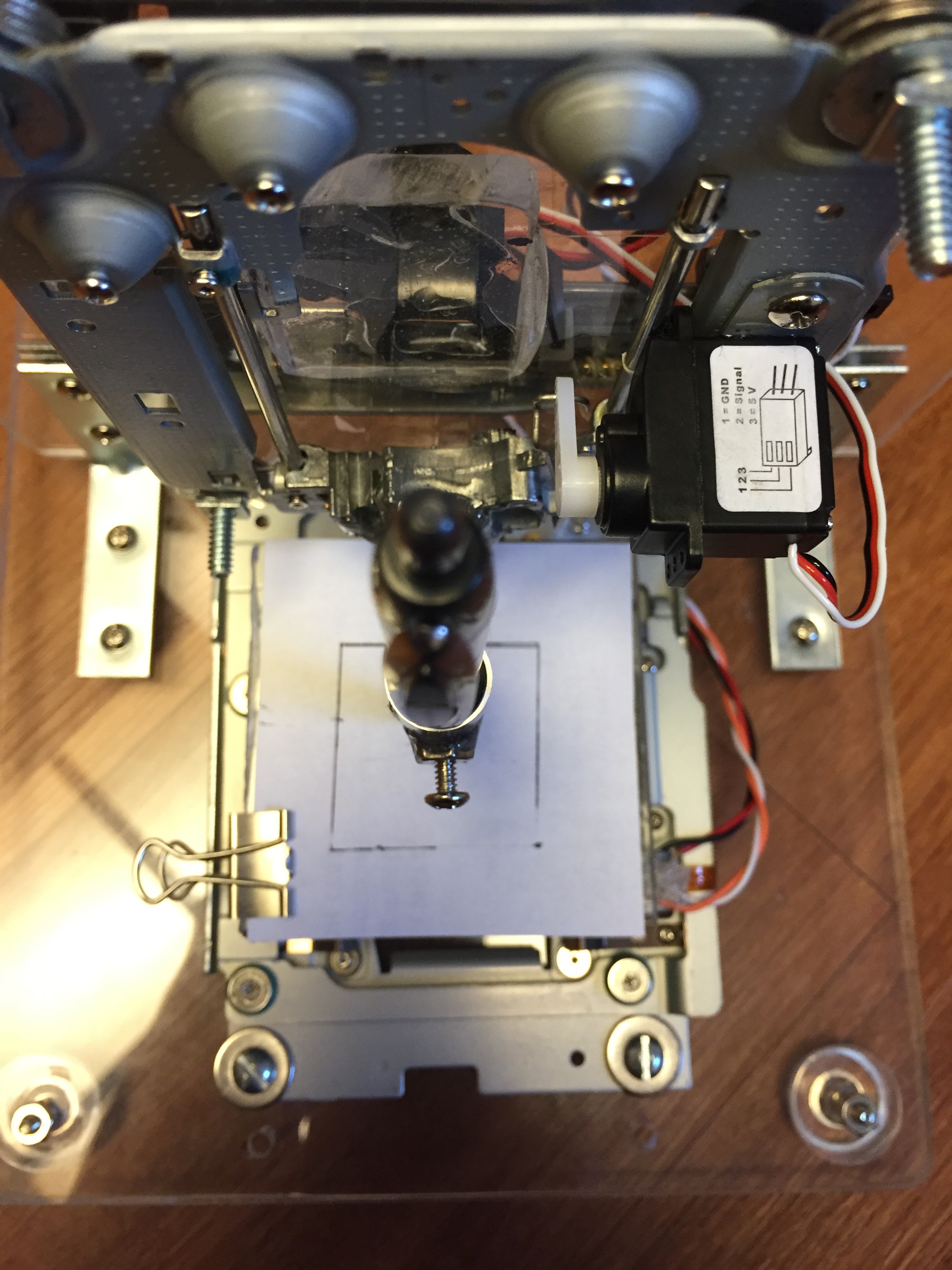
So Day 2 of this CNC machine build I needed to tackle the Z axis. The Z axis took a little more thinking. Most project archives tended to gloss over this important step. Some had a third DVD ROM drive stepper motor and others used a small servo motor, but basically I just need to design something that made the pen lift off the paper long enough to be re-positioned and then dropped down again. Not as complex a movement as a 3D printer or milling machine just up and down. I also needed some type of system for it to slide on. I decided to mix the two concepts I'd seen and use a third DVD ROM drive slider tray, but then attach a simple servo motor to it instead of a third stepper motor. This would simplify the code and wiring and still give me a factory designed slider system to move on. Here's what I ended up with.
Day 3
On day three the challenge was to figure out how to attach the Z Axis servo motor chassis to the Y axis stepper motor chassis, build a drawing platform for the X axis and align everything to be perfectly square. No problem...
X Axis Drawing Platform
 So the drawing platform needed to be a little higher than where the laser had been so I added a little wooden block for height. Then I cut a piece of plexiglass the size of the paper I'd be using 75mm x 75mm StickyNote size. But the plexiglass on the wood just didn't look quite right. I added a little metal disk that came out of one of the DVD drive cases that had an "R 2" stamped in it. I'm not a huge Star Wars nut, but come on!... That's rad. Epoxied it all together and ensured that it was square and aligned as it dried.
Stepper Wiring
I figured that before I glued the whole thing together I'd better get the stepper motors wired up while I still had access to their terminals. The stepper motors are a 2 Phase motor which makes them a little more complicated to work with, but a lot more powerful once you start programming. In the DVD ROM drive they are attached with ribbons which will not work for us as we need wires to connect to the Arduino Motor Controller board mentioned earlier. With a multi-meter you're able to determine which two wires complete a circuit for each phase. These need to be matched pairs in order to run the motors correctly. Once you determine this you need to solder new wires to the terminals without jumping terminals with a big old glob of solder. So I soldered them on and tested them one more time to ensure I hadn't jumped anything at the terminals. Success! As instructed on several tutorials I added a glob of hot glue to add a bit of strength and to keep the soldered terminals from corroding over time.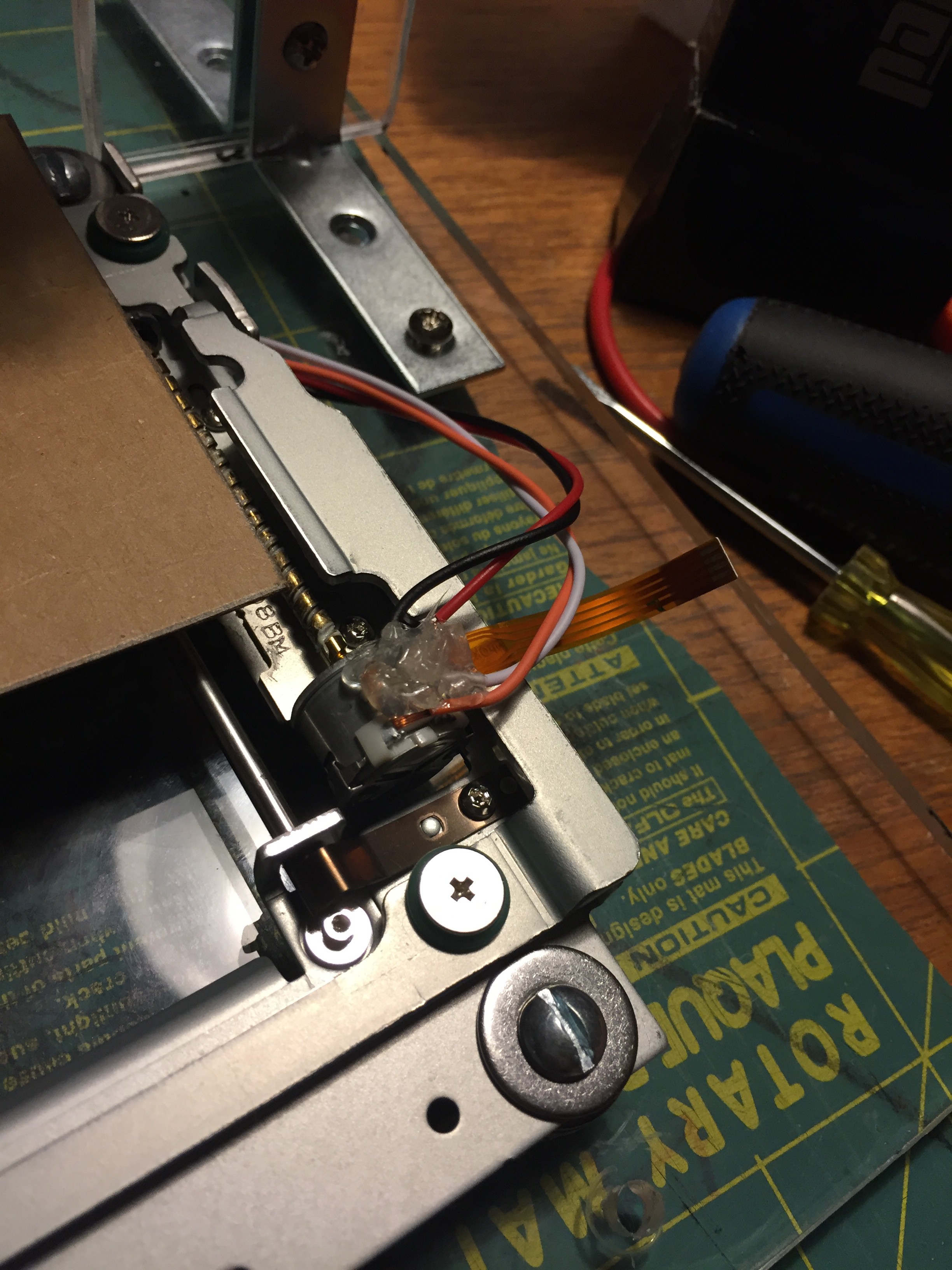 After soldering the X axis stepper motor terminals I repeated the process for the Y axis stepper motor as well.
Z Y Bonding
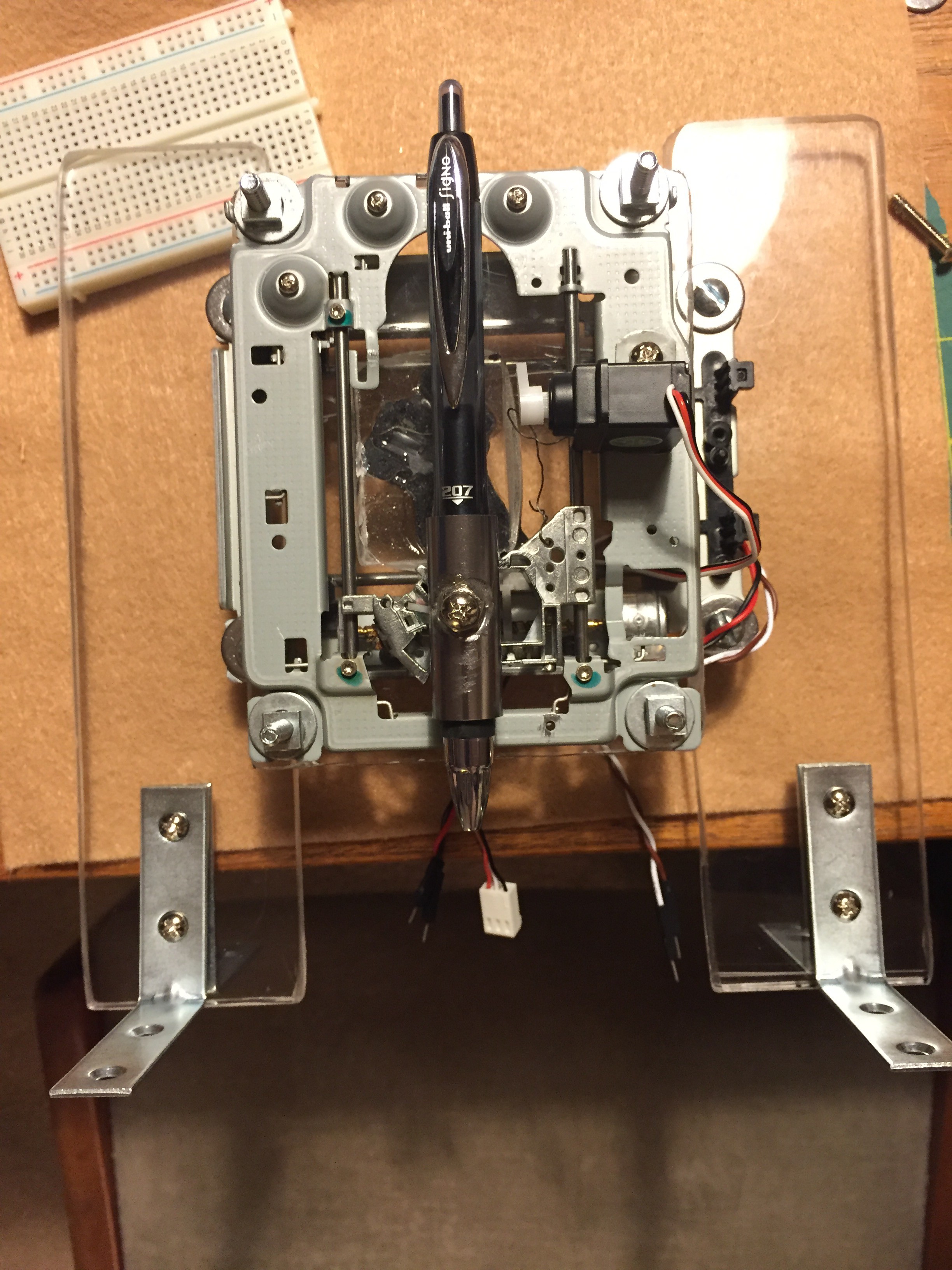
Now we were ready to match up the Z and Y axis' and get them locked together with more epoxy. This was a pretty straight forward process although it took some figuring to ensure the maximum travel allowance in both the left and right directions. I added a bit of space with another small block of plexiglass behind the main Z axis chassis to allow clearance around the motor as it moved left to right and it also brought the pen position further out into the centre of the X axis drawing platform. Oh yeah...the pen...
Pen Holder
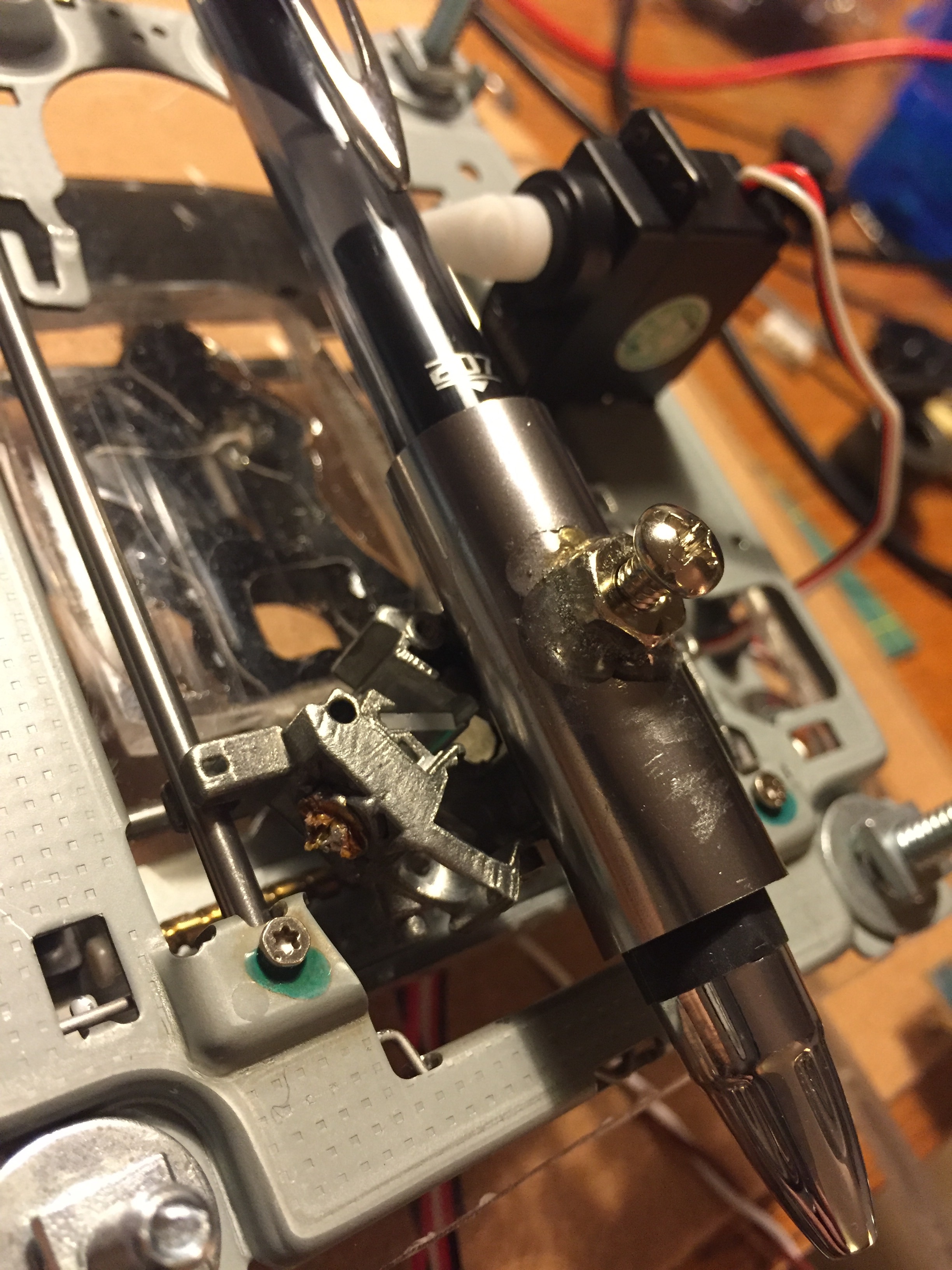
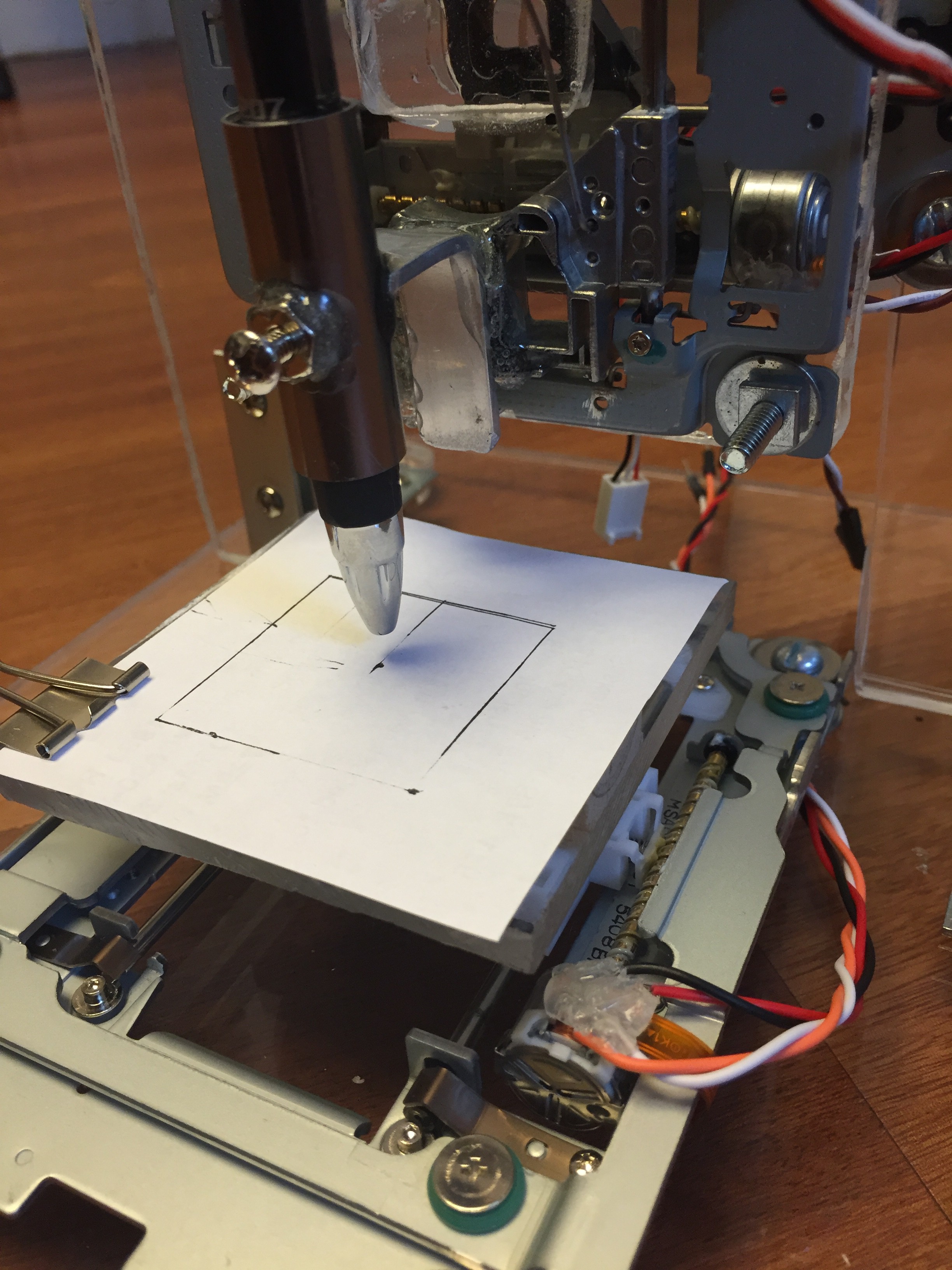
Now the pen needed to be attached to Z axis chassis. I used a small bar of aluminum and bent it into a 90 degree angle and filed a round cradle out of one end. I then took the body from a $1 LED flashlight and drilled a hole in the side of it. I epoxied a nut just over the hole so that a small bolt could be threaded into the nut and protrude through the flashlight body thus trapping a pen inside the tube. This makes the pen height adjustable and also allows us to switch the pen out easily for different types and colours. The flashlight tube is then epoxied into the cradle of the bent aluminum bar which is in turn epoxied to the Z axis chassis.
This completes the CNC fabrications and assembly for the time being. Next up will be the circuitry and programming once my controller shield arrives.